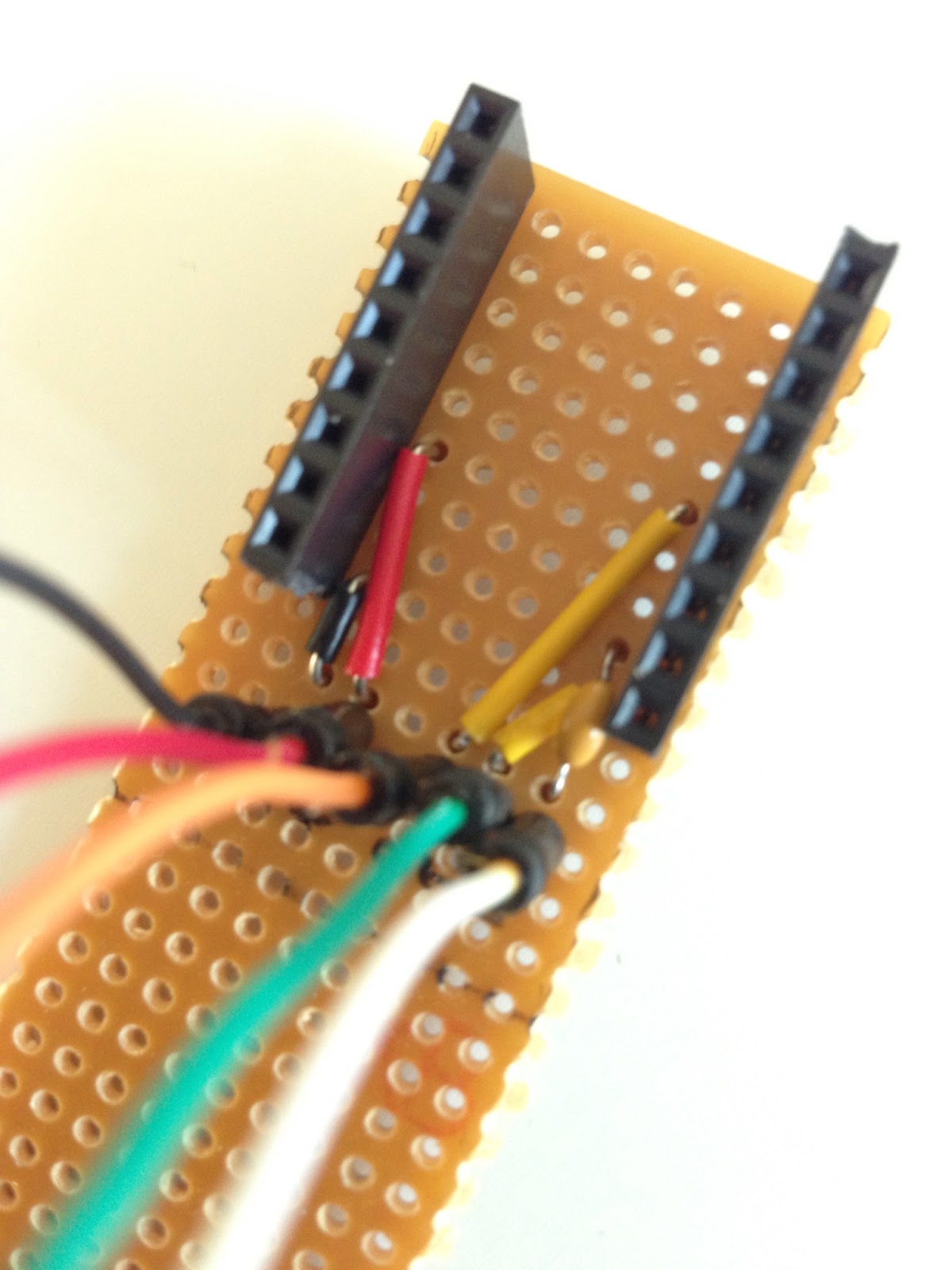
Made a Quick n' dirty jig to fit my Sparkfun FT232RL break out board. I found it a tad bit annoying to always having to unplug and flip board to check and double check the connectors when uploading new code to stand alone ATmega projects.
Basically it brings out the VCC, GND, RXD, TXD and DTR (via a 0.1 uF cap) pins to jumper cables. I'll probably add some labels later.
One end of the jumper cables permanently soldered to the jig and the other end resting in the perfboard holes.
Under the board is the pretty simple circuit with the oh so important 0.1 uF capacitor that goes between the ATmega reset pin and the FT232RL DTR pin.
Ready and hooked up to a ATmega328P on a breadboard.
Finished Atari Punk Console in a Coleman's Mustard Powder can.
Declaration of contents on the back.
Obligatory video.
I based my circuit on these two schematics. Since I only had 555 chips and not a 556 I started with the first schematic but used the 1M Ohm pots from the last one and everything after the 10 uF capacitor. I guess I just liked the sound of the 1 M Ohm pots better. I also added a powerswitch and a LED to indicate ON/OFF.
In a rather unsuccessful attempt to interest my two and a half year old in the world of making stuff, I showed her an episode of "Sylvia's super awesome maker show". Instead I learned a neat trick that will solve an issue I haven't yet experienced... well at least it seems like a very good solution to a problem I might have in the future.
Anyway here it is: If you solder for instance, battery wires directly onto a perfboard of some sort. Fixate the connection with a dab of hot glue to ensure that the soldered joint doesn't break due to cable movement.
I added some hot glue to my Arduino Standalone Atmega
but I probably should have done this prior to soldering
some of the nearby components.
It may not look very pretty but it does keep the stress-point
of the cable away from the solder joint.
[UPDATE] With my hot glue gun in one hand and a fistful of desire to fixate cables in the other I managed to destroy a potentiometer. I failed to notice a small hole in the potentiometer near the solder tabs and got glue inside the potentiometer, increasing the inertia quite a bit.
When I tried to send the output from a sensor over RF with VirtualWire I quickly learned that it wasn't as simple as one two three.
But eventually I got it working with a little help from the good folks at the Arduino forum.
VirtualWire is a library that makes it really easy to transmit using RF modules. I've successfully used two different kinds of 434 Mhz modules with it but it has support for other types aswell.
The code and comments below are pretty much self explanatory:
/*

Sensor Transmitter
By Markus Ulfberg 2012-07-06

Takes a sensor reading 0-1023
converts it to a char array and sends
to RF receiver unit via VirtualWire

*/

#include <VirtualWire.h>

// LED's
const int ledPin = 13;

// Sensors
const int Sensor1Pin = A2;
// const int Sensor2Pin = 3;

int Sensor1Data;
//int Sensor2Data;
char Sensor1CharMsg[4];

void setup() {

 // PinModes
 // LED
 pinMode(ledPin,OUTPUT);
 // Sensor(s)
 pinMode(Sensor1Pin,INPUT);

 // for debugging
 Serial.begin(9600);

 // VirtualWire setup
 vw_setup(2000);     // Bits per sec


}

void loop() {

  // Read and store Sensor 1 data
  Sensor1Data = analogRead(Sensor1Pin);

  // Convert integer data to Char array directly
  itoa(Sensor1Data,Sensor1CharMsg,10);

  // DEBUG
  Serial.print("Sensor1 Integer: ");
  Serial.print(Sensor1Data);
  Serial.print(" Sensor1 CharMsg: ");
  Serial.print(Sensor1CharMsg);
  Serial.println(" ");
  delay(1000);

  // END DEBUG

 digitalWrite(13, true); // Turn on a light to show transmitting
 vw_send((uint8_t *)Sensor1CharMsg, strlen(Sensor1CharMsg));
 vw_wait_tx(); // Wait until the whole message is gone
 digitalWrite(13, false); // Turn off a light after transmission
 delay(200);

} // END void loop...
/*

Sensor Receiver
By Markus Ulfberg 2012-07-06

Gets a sensor reading 0-1023 in a char array
from RF Transmitter unit via VirtualWire
converts char array back to integer

*/

#include <VirtualWire.h>

// LED's
int ledPin = 13;

// Sensors
int Sensor1Data;

// RF Transmission container
char Sensor1CharMsg[4];

void setup() {
  Serial.begin(9600);

  // sets the digital pin as output
  pinMode(ledPin, OUTPUT);

    // VirtualWire
    // Initialise the IO and ISR
    // Required for DR3100
    vw_set_ptt_inverted(true);
    // Bits per sec
    vw_setup(2000);

    // Start the receiver PLL running
    vw_rx_start();

} // END void setup

void loop(){
    uint8_t buf[VW_MAX_MESSAGE_LEN];
    uint8_t buflen = VW_MAX_MESSAGE_LEN;

    // Non-blocking
    if (vw_get_message(buf, &buflen))
    {
    int i;
        // Turn on a light to show received good message
        digitalWrite(13, true);

        // Message with a good checksum received, dump it.
        for (i = 0; i < buflen; i++)
    {
          // Fill Sensor1CharMsg Char array with corresponding
          // chars from buffer.
          Sensor1CharMsg[i] = char(buf[i]);
    }

        // Null terminate the char array
        // This needs to be done otherwise problems will occur
        // when the incoming messages has less digits than the
        // one before.
        Sensor1CharMsg[buflen] = '\0';

        // Convert Sensor1CharMsg Char array to integer
        Sensor1Data = atoi(Sensor1CharMsg);


        // DEBUG
        Serial.print("Sensor 1: ");
        Serial.println(Sensor1Data);

        // END DEBUG

        // Turn off light to and await next message
        digitalWrite(13, false);
    }
}
Soldered up my first standalone ATmega Arduino yesterday.
It's only running the blink sketch right now but I will soon add a RF transmitter and a sensor...
... and solder up yet another add a RF receiver and some sort of notification.
I finally go some time and some inspiration to update the source code of my Arduino Mood Light Controller. I'll just try to keep it short ...
Code cleanup:
All the light modes have been moved to separate functions.
Replaced a couple of "If, then..." with "Switch, Case", makes the code somewhat easier to read.
New features:
Added two light modes - cycleColor and lightMyFire.
Speed of pulsateColor and cycleColor now controlled via potentiometer.
So my laptop fan started rattling recently. First I thought it might be my hard drive that was about to give up, so I was kind of glad it was "just" the fan. Until the noise of the fan started to drive me slightly insane. My first attempt of silencing the fan was a failure. I opened up my laptop and cleaned out all the dust in the fan and the vents. I also checked if there any loose pieces of something in the fan, but didn't find anything. After putting the laptop back together again it didn't take long for the fan to start making noise again.
So yesterday evening I opened up my laptop again, about a month after my initial try. I took it one step further this time, I removed the fan completely and disassembled it up til the point where I had the fan blades removed from the housing. After cleaning everything as good as possible I put a drop of oil (for sewing machines) on the spindle where the fan blades sit. When I had put everything back togheter I could verify that my laptop now indeed was quiet as a mouse. And yes before you ask, the fan i still working.
Unfortunately I didn't take any pictures of this but hopefully it's quite easy to understand anyway. If you don't please just ask and I will try to give you an answer.