Since my daughter comes from a long line of droppers her Lucia candle didn't get much mileage before she dropped it and broke the glass bulb. Glass bulb you say, yes. These hand held electric candles haven't seen much product development in the last thirty years or so.
Lucia is a typical Swedish holiday that combines our favourite pastimes mys* and fika**. Usually it's celebrated by a Lucia train err... a better translation would probably be Lucia procession.
* Mys: activity that makes you feel all warm an fuzzy inside i.e. cozy ** Fika: Eating various types of buns and cookies while consuming either coffee, tea or other seasonal beverage.
Anyway as I was picking up the shards I wondered why they didn't use LEDs for kids candles. But a manufacturers apparent failure to satisfy its customers is a perfect reason for a maker to take things into her or his own hands.
But just using a LED wouldn't be very fun, no we definitely need more awesomeness!
Circuitry
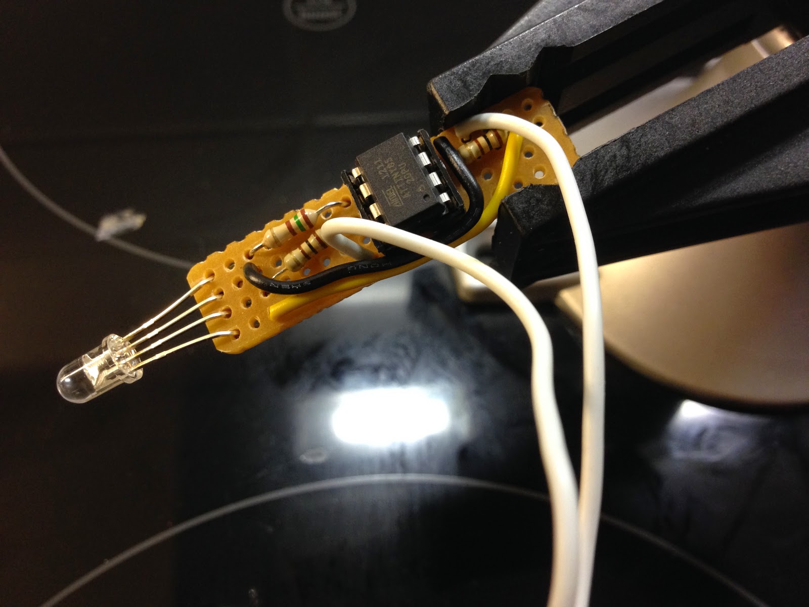
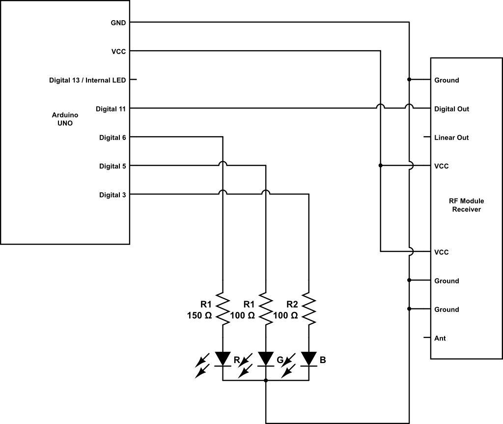
Below is the circuit I designed for this project. It's really simple but I did run into some problems when I realized the ATtiny85 only has 2 PWM outputs. Turns out I was wrong it actually has 4 PWM outputs but two of them share the pin with analog input. Since no input is used in this project that wasn't a problem at all.
Please note: There is one major flaw with my circuitry. I calculated the resistors using the 5V output voltage on the Arduino board. Since this is meant to be powered from standard 1.5V button cell batteries it is far from ideal preferably I should have calculated the resistors for 4.5V. However it actually does work with as low as 3V but the colors are a bit off and dim.
Simple circuit using the ATtiny85 microcontroller, an RGB LED and some resistors.
Breathing life into a flame
Ok, so we have the circuit down, now we need some code to run on the microcontroller. I've written a very short code snippet which uses simple randomness to create a flickering effect. Since there are differences in LEDs you might have to fine tune it according to your hardware, however it should be a pretty simple job as the code is pretty much self explanatory and commented where needed.
/*
  Flickering Candle
  Emulates a candle flickering with a RGB LED
  By Markus Ulfberg 2013-02-01
  Updated: 2014-11-24

  Uses ATtiny85

*/

// Depending on your board, comment out either the ATtiny85/Arduino
// pin variables below.

// LED pins Arduino Board
// int ledRed = 3;
// int ledGreen = 5;
// int ledBlue = 6;

// LED pins Attiny85
int ledRed = 0;  // Chip pin 5
int ledGreen = 1; // Chip pin 6
int ledBlue = 4; // Chip pin 3


// LED Power variables
byte redPwr = 0;
byte greenPwr = 0;
byte bluePwr = 0;

void setup()
{
  pinMode(ledRed, OUTPUT);
  pinMode(ledGreen, OUTPUT);
  pinMode(ledBlue, OUTPUT);

}

void loop()
{

      lightMyFire();

} // END loop()

void lightMyFire() {

  // Flicker will determine how often a fast flare will occur
  int flicker;

  // set flicker randomness
  flicker = random(800);

  // Set color of fire, use a short range to make emulate the
  // smooth movement of a flame.

  // Flicker up
  // when flicker occur, the colors shine brighter
  // adding blue creates a white shine
  if (flicker > 750) {
    redPwr = 255;
    greenPwr = 55;
    bluePwr = 5;
  }

  // Flicker down
  // when flicker occur, the flame goes down in intensity
  // and towards a reddish tone
  if (flicker < 20) {
  redPwr = random(60, 70);
  greenPwr = random(5, 15);
  bluePwr = 0;

  // Main flame color
  } else {

  redPwr = random(190, 200);
  greenPwr = random(40, 50);
  bluePwr = 0;
  }
  // display Colors
  colorDisplay();

  // Set speed of fire
  // The randomness of the delay creates a more natural erratic flame
  delay(random(30, 200));

} // END lightMyFire

// Displays the colors when called from lightMyFire
void colorDisplay() {
  analogWrite(ledRed, redPwr);
  analogWrite(ledGreen, greenPwr);
  analogWrite(ledBlue, bluePwr);
}
Programming the ATtiny85 using the Arduino as ISP.
Running the sketch on the ATtiny85, drawing only power from the Arduino.
Building a better candle
I've spent two years trying to make the circuit fit inside the original candle. It's not really that hard but I've restarted this project just in time to realize I won't make the deadline of Lucia and then my interest faded and I shelved the project until next year.
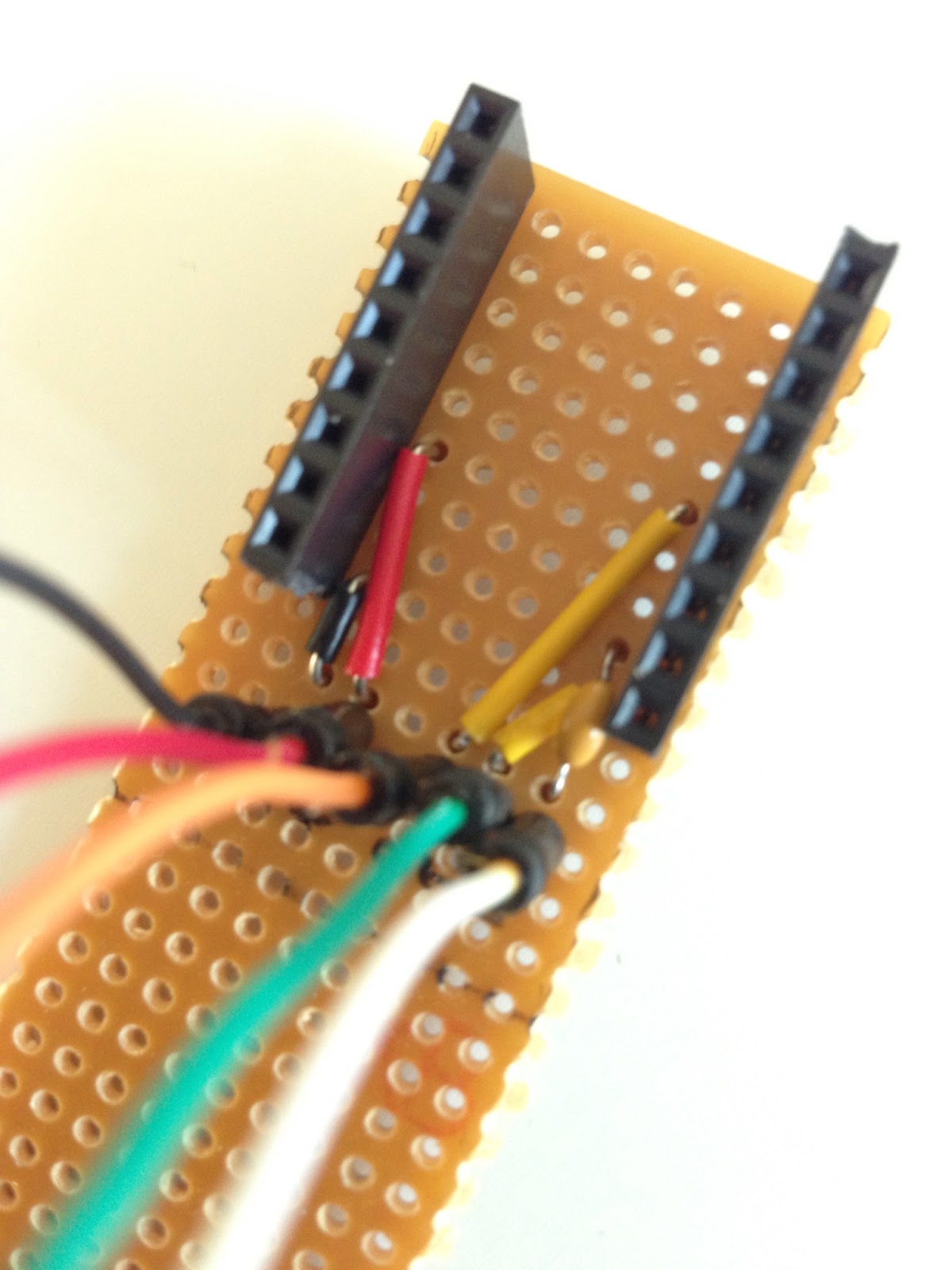
Last year I made this little circuit by cutting a small strip of perfboard that will fit inside the candle body.
Almost done, just need to add power.
Bottom of unfinished circuit on perfboard.
Moving on ...
Some of the main problems that I didn't solve last year was finding a good ON/OFF switch, making a suitable power pack and some sort of diffuser for the LED.
For the ON/OFF switch I decided to take easy way out and just skip it. I could always add it later if I come across a small enough SPST switch. As for power I soldered on the existing power cables from the candle to the perfboard.
Adding power connectors, using the existing ones in the candle.
Just another shot of the back of the circuit.
My power pack consists of three 1.5V LR44 button cell batteries. In order to get them to fit the cradle I just moved the spring closer to the bottom. Et voila, we have a very flimsy battery cradle. I'll probably add some plastic or something to make sure they don't rattle around when we actually use the candle.
The three batteries and the spring prior to hot glueing it into place.
Finished cradle, not pretty but it works.
Nasal spray to the rescue
Around October, I got one of the ten mandatory colds that you get during the season. I also decided to try out a new nasal spray that uses only saline. This means you can spray away as much as you like without the drawbacks of normal nasal spray abuse. It also meant that I finally found a good diffuser for the LED. The cap to the nasal spray had a nice shape of semi transparent plastic, just what I needed for my project.
Nasal spray cap used as a diffuser for the RGB LED.
This is the end ... result.
Ok, so up close the color mixing isn't really perfect. I guess we can blame either the diffuser, my code or my inability to use the correct voltage when calculating what resistor to use. But it works and hey, that's the fun part isn't it?
Prologue: I started writing the below post about a year ago but in the end I never really found a solution to the problem and consequently I never finished the post. Sometime it's best to know when to quit, but maybe this project can be of use to you anyway. Or maybe you'll find the solution that I didn't... well if you do please let me know.
Look Ma no wires!
Ok, so I've built an Arduino based Mood Light Controller and I've managed to get my Arduino to send integers over RF with VirtualWire. Finally I've also built my first Arduino Standalone ATmega / Arduino Bare.
Now I've combined the three into one Wireless Arduino Mood Light Controller. To be honest I had two very different projects planned for my Standalone ATmega and the RF part but those sort of became obsolete in my current living situation.
When I first merged the RGB Mood Light code with the RF Receiver code my Arduino kept hanging. Confident in my own coding skills I quickly aimed my blame towards those who write librarys for the Arduino IDE. The good folks in the Arduino forum managed to deflate my swelling ego and pointed out a few flaws in my code before coming to the conclusion that it might be a hardware problem.
"The rise and fall of a ego" is available as a thread in the Arduino forum.
Meanwhile back on earth ...
I moved my question to the General Electronics part of the Arduino forum, this time with a little more humble attitude. After following the instructions of Grumpy_Mike I quickly learned that my problems came from interference caused by using PWM to control the RGB LED. The trick was to swap out the resistors to 1K Ohm resistors in order to minimize the current and the interference it caused. With 1K Ohm resistors everything worked flawless, well except for the LED that got quite dim.
To minimize the interference Grumpy_Mike suggested the use of capacitors and/or ferrite beads. This actually helped a bit but still not good enough.
Improved circuit with capacitors to stop interference caused by PWM.
Above circuit breadboarded on a protoshield.
Kind of messy and lot's of wires that can cause interference.
Apparently the problem with a circuit like this is that every lead and wire is a source of interference.So I was advised to try to make the circuit tidier, shorten leads and hope for the best.
Leads of the LED and resistors trimmed down ...
... and the RF receiver connected via a ferrite bead as well as an added physically distance.
Also the power supplied to the RF receiver is decoupled with a capacitor.
Dead end?
Unfortunately all this helped very little... and I'm sort of stuck. If you do find a solution to this please let me know as I would love to finish this project.
Here's a little unfinished project that got trashed during my last relocation. Rather than playing around with LEDs and sensors this project is actually based on the idea to be both visually appealing and functional. The plan was to make a sort of interface to a media player such as iTunes or Spotify with the use of the Arduino and a proxy like Gobetwino or (the apparently now dead) ASproxy from (the equally dead) Tinker.it.
Since it's been on ice for quite some time, well actually in this case it rather got "iced" in the mafia sense of the word, I thought it was about time to share the concept of the project.
Step 1. Cut shapes of the buttons in a foam of choice.
Step 2. Glue some foil on the back of the buttons and scotch taped a wire
or solder if you're awesome at that.
Step 3. Paint the buttons in a nice color.
Yeah, I never really got around to step 3.
When I started out my intention was to make a simple circuit and a button that either breaks or closes a circuit. But then I started dabbling with capacitive sensing, hence just the one wire in the pictures.
At first I programmed my ATmega328 chips by pulling them from my circuit and placing them in one of my original Arduino boards. Something that is fun once or twice but gets really annyoing when you do it alot. So working from this tutorial I added some female headers to the circuit, dug out my trusty old SparkFun FT232RL breakout board, a 0.1uF capacitor and some jumper cables.
New female headers added to the RST, RX, TX, +V and GND pins.
The circular thing in the upper left corner is a RF Transmitter module.
The Sparkfun FT232RL break out board.
I usually placed the FT232RL break out board on a breadboard hooked up jumper cables to the corresponding pins of the ATmega. Recently I built a quick n' dirty jig with headers to hold the break out board and permanently soldered jumper cables.
You can see more pictures and read about the build here
This saves me the use of a breadboard and the tedious task of having to flip the FT232RL over numerous times to check and double check the connections.
Issues:
avrdude: stk500_getsync(): not in sync: resp=0x1e
In Arduino IDE I used the board "Duemilanove w/ ATmega328" but kept getting the above error message. At this point I hadn't added the 0.1uF capacitor in series with the DTR pin on the FT232RL to the Reset pin on the ATmega328 so when I googled the error code and found this post it was the first thing I added. But things still wouldn't work. Until I changed my board to "Arduino Uno". After that everything worked like a charm.
Made a Quick n' dirty jig to fit my Sparkfun FT232RL break out board. I found it a tad bit annoying to always having to unplug and flip board to check and double check the connectors when uploading new code to stand alone ATmega projects.
Basically it brings out the VCC, GND, RXD, TXD and DTR (via a 0.1 uF cap) pins to jumper cables. I'll probably add some labels later.
One end of the jumper cables permanently soldered to the jig and the other end resting in the perfboard holes.
Under the board is the pretty simple circuit with the oh so important 0.1 uF capacitor that goes between the ATmega reset pin and the FT232RL DTR pin.
Ready and hooked up to a ATmega328P on a breadboard.
When I tried to send the output from a sensor over RF with VirtualWire I quickly learned that it wasn't as simple as one two three.
But eventually I got it working with a little help from the good folks at the Arduino forum.
VirtualWire is a library that makes it really easy to transmit using RF modules. I've successfully used two different kinds of 434 Mhz modules with it but it has support for other types aswell.
The code and comments below are pretty much self explanatory:
/*

Sensor Transmitter
By Markus Ulfberg 2012-07-06

Takes a sensor reading 0-1023
converts it to a char array and sends
to RF receiver unit via VirtualWire

*/

#include <VirtualWire.h>

// LED's
const int ledPin = 13;

// Sensors
const int Sensor1Pin = A2;
// const int Sensor2Pin = 3;

int Sensor1Data;
//int Sensor2Data;
char Sensor1CharMsg[4];

void setup() {

 // PinModes
 // LED
 pinMode(ledPin,OUTPUT);
 // Sensor(s)
 pinMode(Sensor1Pin,INPUT);

 // for debugging
 Serial.begin(9600);

 // VirtualWire setup
 vw_setup(2000);     // Bits per sec


}

void loop() {

  // Read and store Sensor 1 data
  Sensor1Data = analogRead(Sensor1Pin);

  // Convert integer data to Char array directly
  itoa(Sensor1Data,Sensor1CharMsg,10);

  // DEBUG
  Serial.print("Sensor1 Integer: ");
  Serial.print(Sensor1Data);
  Serial.print(" Sensor1 CharMsg: ");
  Serial.print(Sensor1CharMsg);
  Serial.println(" ");
  delay(1000);

  // END DEBUG

 digitalWrite(13, true); // Turn on a light to show transmitting
 vw_send((uint8_t *)Sensor1CharMsg, strlen(Sensor1CharMsg));
 vw_wait_tx(); // Wait until the whole message is gone
 digitalWrite(13, false); // Turn off a light after transmission
 delay(200);

} // END void loop...
/*

Sensor Receiver
By Markus Ulfberg 2012-07-06

Gets a sensor reading 0-1023 in a char array
from RF Transmitter unit via VirtualWire
converts char array back to integer

*/

#include <VirtualWire.h>

// LED's
int ledPin = 13;

// Sensors
int Sensor1Data;

// RF Transmission container
char Sensor1CharMsg[4];

void setup() {
  Serial.begin(9600);

  // sets the digital pin as output
  pinMode(ledPin, OUTPUT);

    // VirtualWire
    // Initialise the IO and ISR
    // Required for DR3100
    vw_set_ptt_inverted(true);
    // Bits per sec
    vw_setup(2000);

    // Start the receiver PLL running
    vw_rx_start();

} // END void setup

void loop(){
    uint8_t buf[VW_MAX_MESSAGE_LEN];
    uint8_t buflen = VW_MAX_MESSAGE_LEN;

    // Non-blocking
    if (vw_get_message(buf, &buflen))
    {
    int i;
        // Turn on a light to show received good message
        digitalWrite(13, true);

        // Message with a good checksum received, dump it.
        for (i = 0; i < buflen; i++)
    {
          // Fill Sensor1CharMsg Char array with corresponding
          // chars from buffer.
          Sensor1CharMsg[i] = char(buf[i]);
    }

        // Null terminate the char array
        // This needs to be done otherwise problems will occur
        // when the incoming messages has less digits than the
        // one before.
        Sensor1CharMsg[buflen] = '\0';

        // Convert Sensor1CharMsg Char array to integer
        Sensor1Data = atoi(Sensor1CharMsg);


        // DEBUG
        Serial.print("Sensor 1: ");
        Serial.println(Sensor1Data);

        // END DEBUG

        // Turn off light to and await next message
        digitalWrite(13, false);
    }
}
Soldered up my first standalone ATmega Arduino yesterday.
It's only running the blink sketch right now but I will soon add a RF transmitter and a sensor...
... and solder up yet another add a RF receiver and some sort of notification.
I finally go some time and some inspiration to update the source code of my Arduino Mood Light Controller. I'll just try to keep it short ...
Code cleanup:
All the light modes have been moved to separate functions.
Replaced a couple of "If, then..." with "Switch, Case", makes the code somewhat easier to read.
New features:
Added two light modes - cycleColor and lightMyFire.
Speed of pulsateColor and cycleColor now controlled via potentiometer.
Shortly after I wrote a post about Zombie Showdown at the Arduino forum, Bart had a suggestion on how the game could evolve with graphics. My original idea wasn't really to make a game with graphics but rather with physical input and feedback, but I admit I got a bit tempted to try graphics out. But before I got around to, Bart did. Here's the result of my game with Barts graphics.
/*
  Zombie Showdown
  By Markus Ulfberg 2010-01-12

  'Graphics' ;) added by Bart Lammers 2010-01-22

  More Arduino stuff and future updates of Zombie Showdown at:
  http://genericnerd.blogspot.com

  Description:
    A small game using an 16x2 LCD and a pushbutton.
    The game presents a start screen and awaits player input.
    If the player presses the button the game starts.

    After a random number of milliseconds a Zombie will
    appear. It will have a random strenght of 1-5.
    The strenght of the Zombie is equal to how many
    buttonpresses it takes to kill it.

    If the player fails to kill the Zombie within a random
    timeframe the Zombie will kill the player.

    If the player manages to kill the Zombie the game will
    continue and a new Zombie will soon attack.

    When the player dies a Game Over screen is presented
    also displaying the score of the player.

    There is no "beating" this game since in the Zombie apocalypse
    eventually everyone will die.

  Planned expansion:
    1. Use a vibrator to signal Zombie attack.
    2. Use randomizer to make

  Credits:
    This game uses example code from
    Debounce and the LiquidCrystal library.

*/


// include the library code:
#include <LiquidCrystal.h>


// initialize the library with the numbers of the interface pins
LiquidCrystal lcd(7, 8, 9, 10, 11, 12);


// Set the text strings used in the game
char* gameText[]={"Zombie Showdown",// 0 Title
                  "Kill to Start",  // 1
                  "Let's go!",      // 2
                  "Zombie!!!",      // 3
                  "You killed it.", // 4
                  "You are dead.",  // 5
                  "Game Over",      // 6
                  "Score: "         // 7
                  };

// Custom characters for the zombie graphics
byte zombie_head[8] = {
  B00000,
  B00110,
  B01111,
  B11101,
  B11111,
  B11100,
  B11011,
  B11110,
};

byte zombie_body[8] = {
  B11100,
  B11111,
  B11111,
  B11100,
  B11100,
  B11100,
  B11100,
  B11100,
};
byte zombie_arm[8] = {
  B00000,
  B11110,
  B11111,
  B00001,
  B00000,
  B00000,
  B00000,
  B00000,
};

byte zombie_head_expl[8] = {
  B00000,
  B00000,
  B00000,
  B00000,
  B00000,
  B01000,
  B11011,
  B11110,
};

// Button variables
const int buttonPin = 2;

// Two values for debounceing
int buttonState;
int lastButtonState = LOW;

// the following variables are long's because the time, measured in miliseconds,
// will quickly become a bigger number than can be stored in an int.
long lastDebounceTime = 0;  // the last time the output pin was toggled
long debounceDelay = 50;    // the debounce time; increase if the output flickers

// Stores value of button 1 = pressed 0 = released
int buttonPress = 0;

// Title screen blink variables
long lastBlinkTime = 0;
long blinkDelay = 500;
int blinkState = 0;

// Gameplay variables

// Zombie health a random number between 1 and 5
int zombie;

// Time since last zombie apperance
long lastZombieTime = 0;

// Randomizes between each zombie
// Timer for next zombie apperance
// a random number between 200 ms and 20 000 ms
long zombieDelay;

// Randomizes between each zombie
// Countdown timer for zombie bite
// a random number between 2 000 ms and 7 000 ms
long zombieBite;

// Status of zombie apperance 1 = zombie 0 = no zombie
int zombieState = 0;

// Total steps the zombie can take
int zombieSteps = 15;
int zombiePosition = 0;
int zombieLastPosition = 0;
int zombieSpeed = 0;

// Status of player 1 = alive 0 = dead
int playerAlive = 1;

// gameRun sets start screen or runs the game
int gameRun = 0;

// Score
int score = 0;

void setup() {

  // set up the LCD's number of rows and columns:
  lcd.begin(16, 2);

  // DEBUG ONLY
  Serial.begin(9600);

  // Set up the button
  pinMode(buttonPin, INPUT);
  buttonState = digitalRead(buttonPin);

  // Use unconnected analog input pin
  // to generate a random seed for the random generator
  randomSeed(analogRead(0));

  // Generate zombie characters
  lcd.createChar(0, zombie_head);
  lcd.createChar(1, zombie_body);
  lcd.createChar(2, zombie_arm);
  lcd.createChar(3, zombie_head_expl);

  // The timeframe where a new Zombie appears
  // this first Zombie will have a shorter random time frame
  zombieDelay = random(200,10000);

  // The timeframe for the first zombie bite
  zombieBite = random(2000,7000);
  setZombieSpeed();

}

void loop() {

  // Start sequence
  gameStart();

  // Gameplay
  gameExecute();

  // GameOver
  gameOver();

} // loop end

void gameStart() {

  while (gameRun == 0) {
    // Set the cursor
    lcd.setCursor(0,0);

    // print the name of the game
    lcd.print(gameText[0]);


    // Pause for blink
    if ((millis() - lastBlinkTime) > blinkDelay) {

      // If blinkState is OFF turn it ON
      if (blinkState == 0) {

        // Clear the LCD and set the cursor
        lcd.clear();

        // move the cursor down
        lcd.setCursor(0,1);
        // print the blinking text
        lcd.print(gameText[1]);

        // Set the cursor for non blinking text
        lcd.setCursor(0,0);

        // since blink cleared the whole LCD
        // we need print the name of the game again
        lcd.print(gameText[0]);

        // set blinkState to ON
        blinkState = 1;
      // If blinkState is OFF turn it ON
      } else {

        // Clear the LCD and set the cursor
        lcd.clear();


        // Set the cursor for non blinking text
        lcd.setCursor(0,0);

        // print the name of the game
        lcd.print(gameText[0]);

        // Set blink to OFF
        blinkState = 0;

      } // END: else

      // store the new blink time
      lastBlinkTime = millis();


    } // END: if ((millis() - lastBlinkTime) > blinkDelay)

    // Check if button is pressed
    if (button() == 1) {
      // If so start the game
      gameRun = 1;
      playerAlive = 1;

      // reset score
      score = 0;
    } // END: if (button() == 1)

  } // END: while game start
} // END: void gameStart

void gameExecute() {
  // check wether button is pushed to run game
  while (gameRun == 1) {
      lcd.clear();
      lcd.print(gameText[2]);
      // small delay to get ready
      delay(2000);

      // Check if a zombie is here
      if (zombieState == 1) {
        // tell the player that a zombie is here
        lcd.clear();
        // lcd.print(gameText[3]);
        // Put the zombie in position 0;
        drawZombie();

        // Set the strenght and speed of of the zombie
        zombie = random(1,5);

         // Resets the zombie timer
         // this one is for the speed of which the zombie attacks
         lastZombieTime = millis();

        // The action part
        while (zombie > 0) {
         // Find out where the zombie has to stand
         zombiePosition = ((millis() - lastZombieTime) / zombieSpeed);

         if (zombiePosition != zombieLastPosition) {
            // If it moved, redraw
            zombieLastPosition = zombiePosition;
            drawZombie();
         }

         /* // DEBUG
         Serial.print("Str: ");
         Serial.print(zombie, DEC);
         Serial.print(" Time: ");
         Serial.print(zombieBite);
         Serial.print(" Bite: ");
         Serial.println((millis() - lastZombieTime));
         */ // END: DEBUG

         // Check if button is pressed
         if (button() == 1) {
           // If so remove 1 health from zombie
           zombie--;
         }

         // check if the zombie bites
         if ((millis() - lastZombieTime) > zombieBite) {

           // player is bitten and killed
           // Print information on death
           lcd.clear();
           lcd.print(gameText[5]);
           delay(2000);

           // Make sure all loops are exited
           gameRun = 0;
           zombie = 0;
         }

       } // END: while zombie > 0

       // Add score, first check if the zombie was killed or
       // it was the player who died and zombie was just reset
       if (gameRun == 1) {
         // The zombie was killed
         zombieState = 0;
         // Add to the players score
         score++;
         //lcd.clear();
         // Print information of kill
         //lcd.print(gameText[4]);
         lcd.setCursor(zombiePosition,0);
         lcd.write(3);
         // Pause for a while
         delay(1000);
       }

     } else { // END: if Zombie State and Start else

       // zombieState is 0 check if enough time
       // has passed since last zombie
       if ((millis() - lastZombieTime) > zombieDelay) {
         // A new zombie is here
         zombieState = 1;
         // reset random zombieDelay
         zombieDelay = random(200,2000);

         // reset random zombieBite time;
         zombieBite = random(2000,7000);
         setZombieSpeed();

         // reset position
         zombiePosition = 0;
         zombieLastPosition = 0;

       } // END: if ((millis() - lastZombieTime) > zombieDelay)

     } // END: else

  }  // END: while game run

} // END: gameExecute

// Calculate the zombie speed, how many ms per step?
void setZombieSpeed() {
  zombieSpeed = zombieBite / zombieSteps;
}

// Draw the zombie on the screen in the correct position
void drawZombie() {
 lcd.clear();
 lcd.setCursor(zombiePosition,0);
 lcd.write(0);
 lcd.setCursor(zombiePosition,1);
 lcd.write(1);
 lcd.setCursor(zombiePosition+1,1);
 lcd.write(2);
}

int button() {
  // read the state of the switch into a local variable:
  int reading = digitalRead(buttonPin);

  // check to see if you just pressed the button
  // (i.e. the input went from LOW to HIGH),  and you've waited
  // long enough since the last press to ignore any noise:

  // If the switch changed, due to noise or pressing:
  if (reading != lastButtonState) {
    // reset the debouncing timer
    lastDebounceTime = millis();
  }

  if ((millis() - lastDebounceTime) > debounceDelay) {
    // whatever the reading is at, it's been there for longer
    // than the debounce delay, so take it as the actual current state:
    buttonState = reading;

    // If button is pressed down
    if (buttonState == HIGH) {
      // store the state of the button
      buttonPress = 1;
    }
    // If button is up ...
    if (buttonState == LOW) {
      // ... and was just down i.e released
      if (buttonPress == 1) {
        // Store the new state of the button
        buttonPress = 0;

        // also save the reading since we terminate in the next step
        lastButtonState = reading;

        // Terminate the button() function and return
        // a positive button press
        return 1;
      }
    } // END: If buttonState == LOW
  } // END: If millis...

  // save the reading.  Next time through the loop,
  // it'll be the lastButtonState:
  lastButtonState = reading;

} // END: void button()

void gameOver() {
  lcd.clear();
  lcd.setCursor(0,0);
  // Print Game Over
  lcd.print(gameText[6]);
  lcd.setCursor(0,1);
  // Print Score
  lcd.print(gameText[7]);
  lcd.print(score);
  // Pause for a while
  delay(4000);

}
I recently bought a 16x2 LCD from Adafruit and decided to make a small Zombie survival game as my first project.
The hardware is just the LCD hooked up according to instructions on the LCD product page and a push-button with a pull-down resistor like the one in this tutorial.
Here are som pictures and a movie from the project:
/*
  Zombie Showdown
  By Markus Ulfberg 2010-01-12

  More Arduino stuff and future updates of Zombie Showdown at:
  http://genericnerd.blogspot.com

  Description:
    A small game using an 16x2 LCD and a pushbutton.
    The game presents a start screen and awaits player input.
    If the player presses the button the game starts.

    After a random number of milliseconds a Zombie will
    appear. It will have a random strenght of 1-5.
    The strenght of the Zombie is equal to how many
    buttonpresses it takes to kill it.

    If the player fails to kill the Zombie within a random
    timeframe the Zombie will kill the player.

    If the player manages to kill the Zombie the game will
    continue and a new Zombie will soon attack.

    When the player dies a Game Over screen is presented
    also displaying the score of the player.

    There is no "beating" this game since in the Zombie apocalypse
    eventually everyone will die.

  Planned expansion:
    1. Use a vibrator to signal Zombie attack.
    2. Use randomizer to make

  Credits:
    This game uses example code from
    Debounce and the LiquidCrystal library.

*/


// include the library code:
#include <LiquidCrystal.h>


// initialize the library with the numbers of the interface pins
LiquidCrystal lcd(7, 8, 9, 10, 11, 12);


// Set the text strings used in the game
char* gameText[]={"Zombie Showdown",// 0 Title
                  "Kill to Start",  // 1
                  "Let's go!",      // 2
                  "Zombie!!!",      // 3
                  "You killed it.", // 4
                  "You are dead.",  // 5
                  "Game Over",      // 6
                  "Score: "         // 7
                  };

// Button variables
const int buttonPin = 2;

// Two values for debounceing
int buttonState;
int lastButtonState = LOW;

// the following variables are long's because the time, measured in miliseconds,
// will quickly become a bigger number than can be stored in an int.
long lastDebounceTime = 0;  // the last time the output pin was toggled
long debounceDelay = 50;    // the debounce time; increase if the output flickers

// Stores value of button 1 = pressed 0 = released
int buttonPress = 0;

// Title screen blink variables
long lastBlinkTime = 0;
long blinkDelay = 500;
int blinkState = 0;

// Gameplay variables

// Zombie health a random number between 1 and 5
int zombie;

// Time since last zombie apperance
long lastZombieTime = 0;

// Randomizes between each zombie
// Timer for next zombie apperance
// a random number between 200 ms and 20 000 ms
long zombieDelay;

// Randomizes between each zombie
// Countdown timer for zombie bite
// a random number between 2 000 ms and 7 000 ms
long zombieBite;

// Status of zombie apperance 1 = zombie 0 = no zombie
int zombieState = 0;

// Status of player 1 = alive 0 = dead
int playerAlive = 1;

// gameRun sets start screen or runs the game
int gameRun = 0;

// Score
int score = 0;

void setup() {

  // set up the LCD's number of rows and columns:
  lcd.begin(16, 2);

  // DEBUG ONLY
  Serial.begin(9600);

  // Set up the button
  pinMode(buttonPin, INPUT);
  buttonState = digitalRead(buttonPin);

  // Use unconnected analog input pin
  // to generate a random seed for the random generator
  randomSeed(analogRead(0));

  // The timeframe where a new Zombie appears
  // this first Zombie will have a shorter random time frame
  zombieDelay = random(200,10000);

  // The timeframe for the first zombie bite
  zombieBite = random(2000,7000);

}

void loop() {

  // Start sequence
  gameStart();

  // Gameplay
  gameExecute();

  // GameOver
  gameOver();

} // loop end

void gameStart() {

  while (gameRun == 0) {
    // Set the cursor
    lcd.setCursor(0,0);

    // print the name of the game
    lcd.print(gameText[0]);


    // Pause for blink
    if ((millis() - lastBlinkTime) > blinkDelay) {

      // If blinkState is OFF turn it ON
      if (blinkState == 0) {

        // Clear the LCD and set the cursor
        lcd.clear();

        // move the cursor down
        lcd.setCursor(0,1);
        // print the blinking text
        lcd.print(gameText[1]);

        // Set the cursor for non blinking text
        lcd.setCursor(0,0);

        // since blink cleared the whole LCD
        // we need print the name of the game again
        lcd.print(gameText[0]);

        // set blinkState to ON
        blinkState = 1;
      // If blinkState is OFF turn it ON
      } else {

        // Clear the LCD and set the cursor
        lcd.clear();


        // Set the cursor for non blinking text
        lcd.setCursor(0,0);

        // print the name of the game
        lcd.print(gameText[0]);

        // Set blink to OFF
        blinkState = 0;

      } // END: else

      // store the new blink time
      lastBlinkTime = millis();


    } // END: if ((millis() - lastBlinkTime) > blinkDelay)

    // Check if button is pressed
    if (button() == 1) {
      // If so start the game
      gameRun = 1;
      playerAlive = 1;

      // reset score
      score = 0;
    } // END: if (button() == 1)

  } // END: while game start
} // END: void gameStart

void gameExecute() {
  // check wether button is pushed to run game
  while (gameRun == 1) {
      lcd.clear();
      lcd.print(gameText[2]);
      // small delay to get ready
      delay(2000);

      // Check if a zombie is here
      if (zombieState == 1) {
        // tell the player that a zombie is here
        lcd.clear();
        lcd.print(gameText[3]);


        // Set the strenght and speed of of the zombie
        zombie = random(1,5);

         // Resets the zombie timer
         // this one is for the speed of which the zombie attacks
         lastZombieTime = millis();

        // The action part
        while (zombie > 0) {

         /* // DEBUG
         Serial.print("Str: ");
         Serial.print(zombie, DEC);
         Serial.print(" Time: ");
         Serial.print(zombieBite);
         Serial.print(" Bite: ");
         Serial.println((millis() - lastZombieTime));
         */ // END: DEBUG

         // Check if button is pressed
         if (button() == 1) {
           // If so remove 1 health from zombie
           zombie--;
         }

         // check if the zombie bites
         if ((millis() - lastZombieTime) > zombieBite) {

           // player is bitten and killed
           // Print information on death
           lcd.clear();
           lcd.print(gameText[5]);
           delay(2000);

           // Make sure all loops are exited
           gameRun = 0;
           zombie = 0;
         }

       } // END: while zombie > 0

       // Add score, first check if the zombie was killed or
       // it was the player who died and zombie was just reset
       if (gameRun == 1) {
         // The zombie was killed
         zombieState = 0;
         // Add to the players score
         score++;
         lcd.clear();
         // Print information of kill
         lcd.print(gameText[4]);
         // Pause for a while
         delay(1000);
       }

     } else { // END: if Zombie State and Start else

       // zombieState is 0 check if enough time
       // has passed since last zombie
       if ((millis() - lastZombieTime) > zombieDelay) {
         // A new zombie is here
         zombieState = 1;
         // reset random zombieDelay
         zombieDelay = random(200,2000);

         // reset random zombieBite time;
         zombieBite = random(2000,7000);

       } // END: if ((millis() - lastZombieTime) > zombieDelay)

     } // END: else

  }  // END: while game run

} // END: gameExecute

int button() {
  // read the state of the switch into a local variable:
  int reading = digitalRead(buttonPin);

  // check to see if you just pressed the button
  // (i.e. the input went from LOW to HIGH),  and you've waited
  // long enough since the last press to ignore any noise:

  // If the switch changed, due to noise or pressing:
  if (reading != lastButtonState) {
    // reset the debouncing timer
    lastDebounceTime = millis();
  }

  if ((millis() - lastDebounceTime) > debounceDelay) {
    // whatever the reading is at, it's been there for longer
    // than the debounce delay, so take it as the actual current state:
    buttonState = reading;

    // If button is pressed down
    if (buttonState == HIGH) {
      // store the state of the button
      buttonPress = 1;
    }
    // If button is up ...
    if (buttonState == LOW) {
      // ... and was just down i.e released
      if (buttonPress == 1) {
        // Store the new state of the button
        buttonPress = 0;

        // also save the reading since we terminate in the next step
        lastButtonState = reading;

        // Terminate the button() function and return
        // a positive button press
        return 1;
      }
    } // END: If buttonState == LOW
  } // END: If millis...

  // save the reading.  Next time through the loop,
  // it'll be the lastButtonState:
  lastButtonState = reading;

} // END: void button()

void gameOver() {
  lcd.clear();
  lcd.setCursor(0,0);
  // Print Game Over
  lcd.print(gameText[6]);
  lcd.setCursor(0,1);
  // Print Score
  lcd.print(gameText[7]);
  lcd.print(score);
  // Pause for a while
  delay(4000);

}
Background I love black and white, especially white. But I also love color, however I tend to change what type of color I like ALOT. So when saw the concept of coloring a surface with light I knew I had to try it at home.
The hardwareI decided to use my new found love the Arduino micro controller to control some sort of light. At first I thought about using IKEAS DIODER but as MikMo pointed out the RGB LED strip from Deal Extreme is quite a much better deal. A little over $16 and free shipping from Hong Kong. What I wanted to achive
Select a specific color
Pulsate the specified color
Random color swash i.e. go smoothly from color to color.
Controlling the colors
I decided to use a ULN2003 with the Arduino to control the DX RGB LED strip. It can handle enough amps to drive the LED strip and it's also alot neater than multiple transistors.
Arduino control of LED strip via ULN2003 RGB LED strip 400 mA @ 12 V R1 = 10K Potentiometer (Color selector) R2 = 100 Ohm (Pin protector)
R3 = 10K Ohm (Pulldown resistor) S1 = Switch (Mode selector)
One potentiometer to rule them all
When I first started out mixing RGB colors I used three potentiometers, one for each color. This ofcourse gives you a high resolution but also three different knobs. So inspired by the Philips LivingColors, I decided to streamline my color control using only one potentiometer connected to an analog in pin on the Arduino.
As you can see in the picture below the value 0 on the analog pin is full red and then changes through the color circle back to red as the value reaches 1023.
Note: I used Adobe Illustrator to create the image above, to help me think, but when using gradient fill in Illustrator some colors take up more space than others. At least it looks like that if you space them evenly. I don't know if this also is the case with my color mixer, but I haven't really bothered to figure that out.
At first I used alot of steps before I realized I could remove some of them. Orange for example is produced when you have more red than green on your way to yellow (full red and full green). But purple requires both full red and full blue. Hence some I could remove some steps and had to keep some of them.
Videos
Button presses in the video
Filmed in broad daylight, hence the colors don't really come out too well.
1. On - Select a color with the color selector.
2. Pulse - Pulsate the selected color.
3. Random/Cycle - Cycle randomly through the palette.
4. Off.
Pulse Mode
Filmed in a dark room with the RGB-strip hidden behind the laptop screen.
Random/Cycle Mode
Filmed in a dark room with the RGB-strip hidden behind the laptop screen.